Setting Up Hardware and Software
🔧 Note: Some elements like board files are currently proprietary. However, we’re building an open version, and your contributions are welcome.
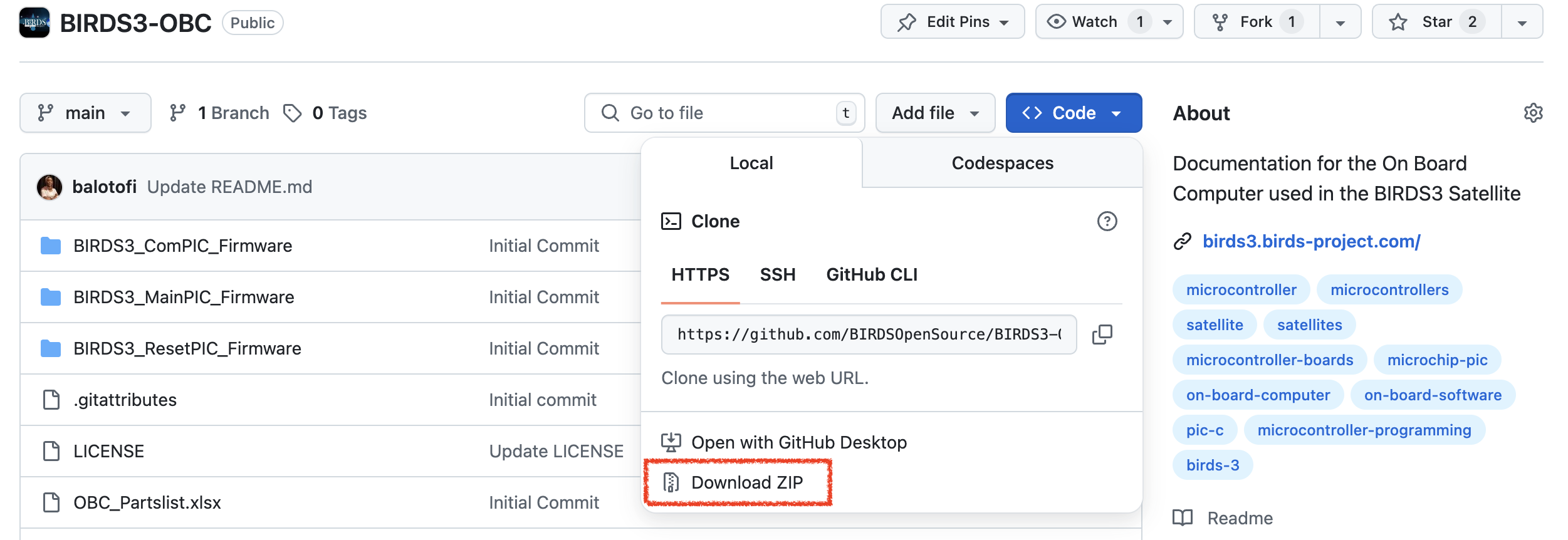
1. Clone the Repository
First, clone the OBC hardware and firmware repositories to your local machine:
git clone https://github.com/BIRDSOpenSource/BIRDS3-OBC.git
Make sure you have git installed. If not, you can download the repository as a ZIP file from GitHub.
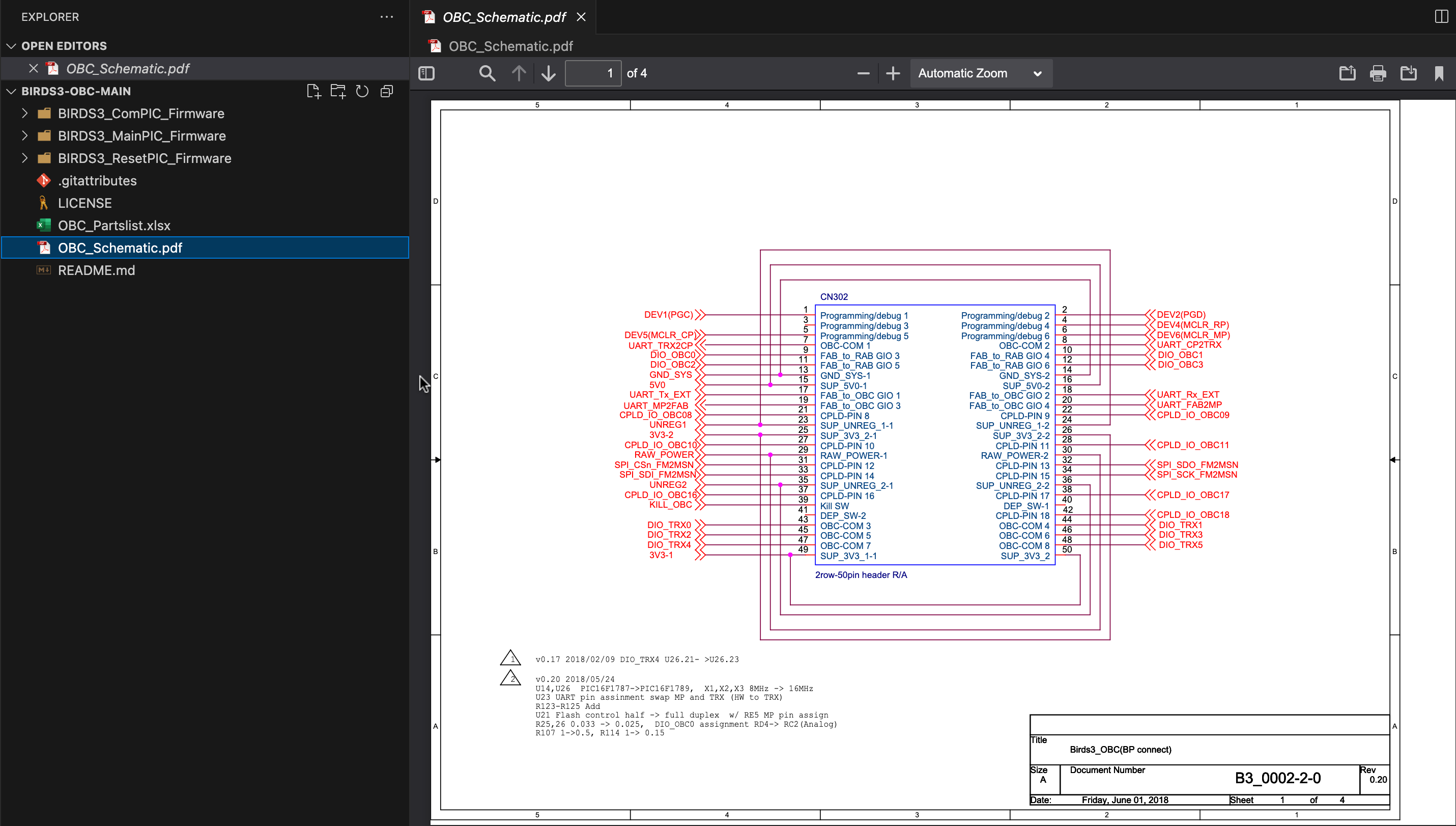
2. Open the OBC Schematics
- In the folder you have downloaded or cloned, navigate to the
OBC_Schematic.pdffile. - Since the board files (
.sch,.brd) are proprietary, only pdf schematics are available at this time for all editions of the BIRDS series.
📢 Want to help? We’re building an open OBC board. Check out the
obc-open-hardwareproject in our Project List to contribute.
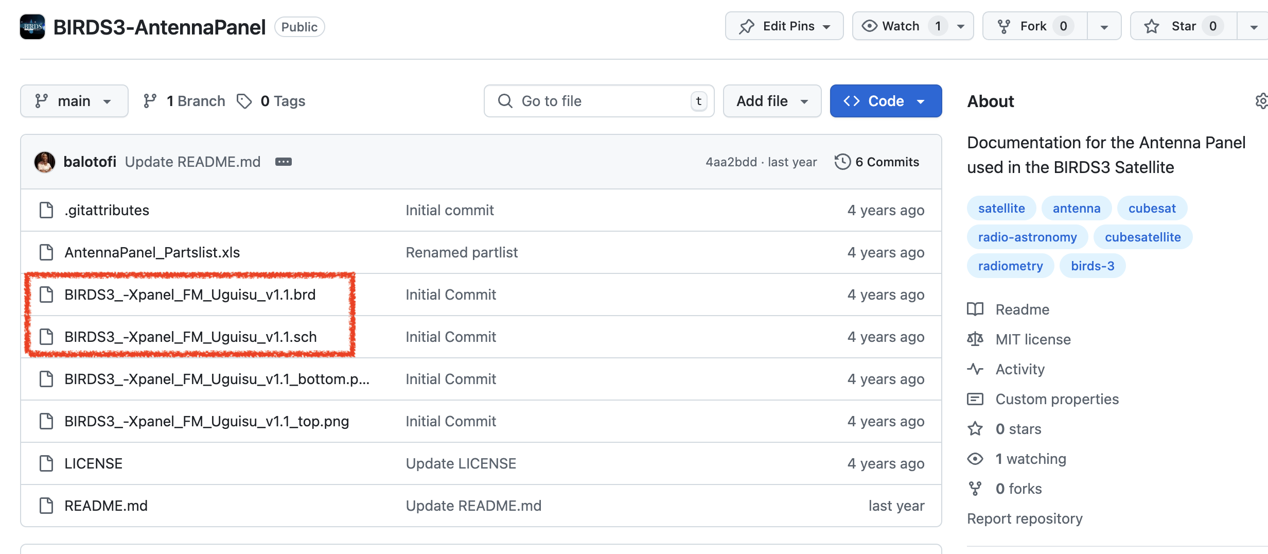
3. PCB Layout & Export (Using Antenna Board as Example)
While the OBC board files aren’t public yet, we recommend trying the antenna panel as a practice project.
Steps:
- Go to the
BIRDS3 Antenna PanelGithub page and download the.brdand.schfiles.
-
Open your PCB designer of choice e.g KiCad, Fusion 360/ Eagle, etc.
-
Open the
.schand.brdfiles in the PCB designer. Follow this tutorial if using Kicad. -
Export Gerber files via File → Plot, and generate drill files via File → Fabrication Outputs.
🔍 Although we use Fusion 360/ Eagle, the antenna panel is fully accessible in KiCad for open testing.
Troubleshooting? Try working with .brd files guide.
You can view the files online here first.
4. Open the Bill of Materials (BOM)
You can find the OBC parts list (OBC_Partslist.xlsx) in the BIRDS3-OBC folder you cloned earlier.
- It includes current and obsolete components.
- We’re developing a solution mapping sheet that suggests updated, drop-in replacements.
🔄 This is a living document. If you find alternatives, please submit a pull request or open an issue.
5. Explore the Firmware
Explore the structure of the PIC firmware in the BIRDS3_MainPIC_Firmware folder.
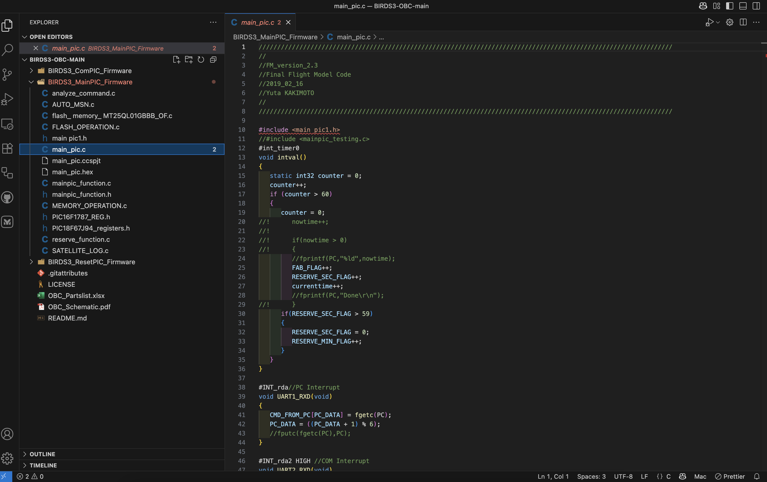
- Each subsystem has its own folder.
- Code comments and function headers guide you through main functionalities.
- The Software Developers Manual (in development) will help clarify more advanced logic.
6. Build and Flash the PIC Microcontroller
You will need:
- MPLAB IPE v6.00 or later (Free to download from Microchip)
- PICkit 3.5 debugger/programmer (since PICkit 3 is obsolete)
- HEX firmware file (typically in the
dist/folder)
Flashing Steps:
- Open MPLAB IPE and select your device (e.g., PIC18F series).
- Choose the PICkit 3.5 as your tool.
- Browse for your
.hexfile. - Click “Connect”, then “Program”.
🛑 Always verify power and orientation before flashing to avoid damaging your board.
7. Troubleshooting Tips
- If MPLAB fails to connect: check USB cable, driver, and power source.
- Ensure that the MCU is not in reset mode or receiving unstable power.
- Cross-check your configuration bits (sometimes mismatches cause boot issues).
- Check if a watchdog timer is unintentionally enabled.
✅ Setting Up Checklist
- Clone the OBC repositories
- Open the schematics in Fusion 360 Electronics
- Review and explore the firmware repository
- Test PCB export using antenna panel in KiCad
- Review the BOM and suggest replacements if possible
- Flash the MCU using MPLAB IPE + PICkit 3.5
- Browse the troubleshooting section and keep notes of your setup
💡 Need help or want to contribute improvements to this guide? Join the discussion on GitHub Discussions.