Background
We are currently in the process of updating much of our training content referencing documents from the BIRDS-X satellite.
- 1. Introduction
- 2. What are the phases of a satellite?
- 3. What is in the BIRDS bus?
- 4. What tools do we use in development?
- Getting Started
1. Introduction
This guide is intended to facilitate a comprehensive understanding of the usage of BIRDS Bus subsystem testing documents, empowering team members and collaborators to follow standardized procedures for reliable subsystem performance.
This document outlines the purpose, structure, and practical steps for using the testing process and procedural guides for subsystems such as the
- On-Board Computer (OBC),
- Electrical Power System (EPS),
- Attitude Determination and Control System (ADCS),
- Communications (COM),
- and the structural components of BIRDS satellites.
We are creating an environment for sharing knowledge and ideas.
To help you create your own open source satellite mission, we are building a library of resources that will cover the entire mission lifetime from start to finish.
If you would want to contribute to, or work with the BIRDS community in order to assist in developing this solution, please contibute to the our Discussions channel on Github or get in touch with us.
2. What are the phases of a satellite?
The development and deployment of a satellite involve a series of carefully structured phases to ensure the mission’s success. From initial concept discussions to final pre-launch verifications, these phases guide teams through designing, building, and testing the satellite to meet stringent space industry standards.
Each phase acts as a checkpoint to confirm that requirements are met and potential risks are mitigated. Understanding the phases - including the
- Mission Definition Review (MDR),
- Preliminary Design Review (PDR),
- Critical Design Review (CDR), and
- Flight Model Testing (FMT) — is essential for satellite teams to manage the complexity of satellite engineering and increase the likelihood of achieving mission goals.
Mission Definition Review (MDR)
- The Mission Definition Review is the initial phase where the primary objectives and feasibility of the satellite mission are assessed. It ensures that the mission concept aligns with stakeholder goals and meets basic feasibility criteria.
-
Key Activities:
- Requirements Definition: Establishing the mission’s main objectives, such as scientific data collection, Earth observation, or communication.
- Concept Analysis: Evaluating different mission concepts and selecting the most viable one.
- Preliminary Budgeting: Outlining initial cost estimates and resource needs.
- Risk Assessment: Identifying potential high-level risks and challenges.
- Outcome: Approval to proceed to the design phase. The outcome of the MDR is a clearly defined mission scope with initial high-level requirements.
Preliminary Design Review (PDR)
- The Preliminary Design Review is a crucial checkpoint to assess whether the preliminary design of the satellite meets the mission’s requirements and objectives. It ensures that the basic design approach is sound before advancing to more detailed design work.
-
Key Activities:
- Subsystem Design Overview: Presenting initial design plans for key subsystems like OBC, EPS, ADCS, COM, payloads, and structure.
- Preliminary Schematics: Showing preliminary circuit diagrams, mechanical layouts, and software architecture.
- Interface Definition: Outlining how different subsystems will interact and integrate.
- Verification Plan: Drafting a plan for how each requirement will be tested and verified in later phases.
- Outcome: Approval to move to detailed design and further development. If the PDR is successful, the project team receives a green light to refine and deepen their designs.
Critical Design Review (CDR)
- The Critical Design Review is an in-depth evaluation of the final design before it transitions into production and assembly. The aim is to verify that the detailed design meets all mission requirements and is manufacturable and testable.
-
Key Activities:
- Detailed Design Presentation: Showcasing detailed drawings, CAD models, circuit layouts, and software implementation.
- Compliance Check: Ensuring that the design adheres to industry standards, regulatory requirements, and internal specifications.
- Risk Mitigation Plans: Reviewing the updated risk register and contingency plans.
- Manufacturing Readiness: Assessing the readiness of production facilities, supply chains, and assembly processes.
- Outcome: Approval to proceed to the manufacturing and integration phase. A successful CDR means that the design is considered final, and the team can start producing and assembling components.
Flight Model Testing (FM)
- Flight Model Testing is the phase where the actual satellite, known as the Flight Model (FM), undergoes a series of rigorous tests to validate its performance under conditions that simulate the space environment. This is the final verification before launch.
-
Key Activities:
- Functional Testing: Verifying that each subsystem and the satellite as a whole function as expected.
-
Environmental Testing:
- Thermal Vacuum (TVT) Testing: Ensuring the satellite can withstand the extreme temperatures and vacuum conditions of space.
- Vibration Testing: Testing for structural integrity under launch conditions to ensure it can survive the launch vibrations.
- Deployment Testing: Verifying the proper deployment of antennas, solar panels, or other movable parts.
- Outcome: Confirmation that the satellite is ready for launch. Any failures during this phase may require redesign, rework, or additional testing until issues are resolved and the satellite meets all operational standards.
Conclusion
These phases create a structured pathway from conceptualization to launch, with each review and testing stage serving as a critical checkpoint. The Mission Definition Review sets the scope, the Preliminary Design Review checks the initial design feasibility, the Critical Design Review finalizes the detailed design, and Flight Model Testing ensures that the satellite is robust and mission-ready. This structured approach helps in mitigating risks, ensuring quality, and promoting mission success.
3. What is in the BIRDS bus?
 |  |
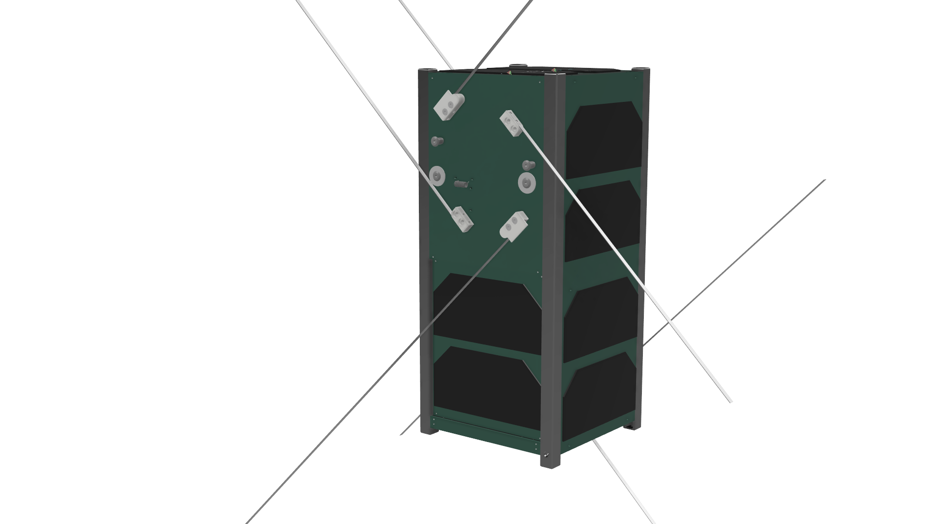
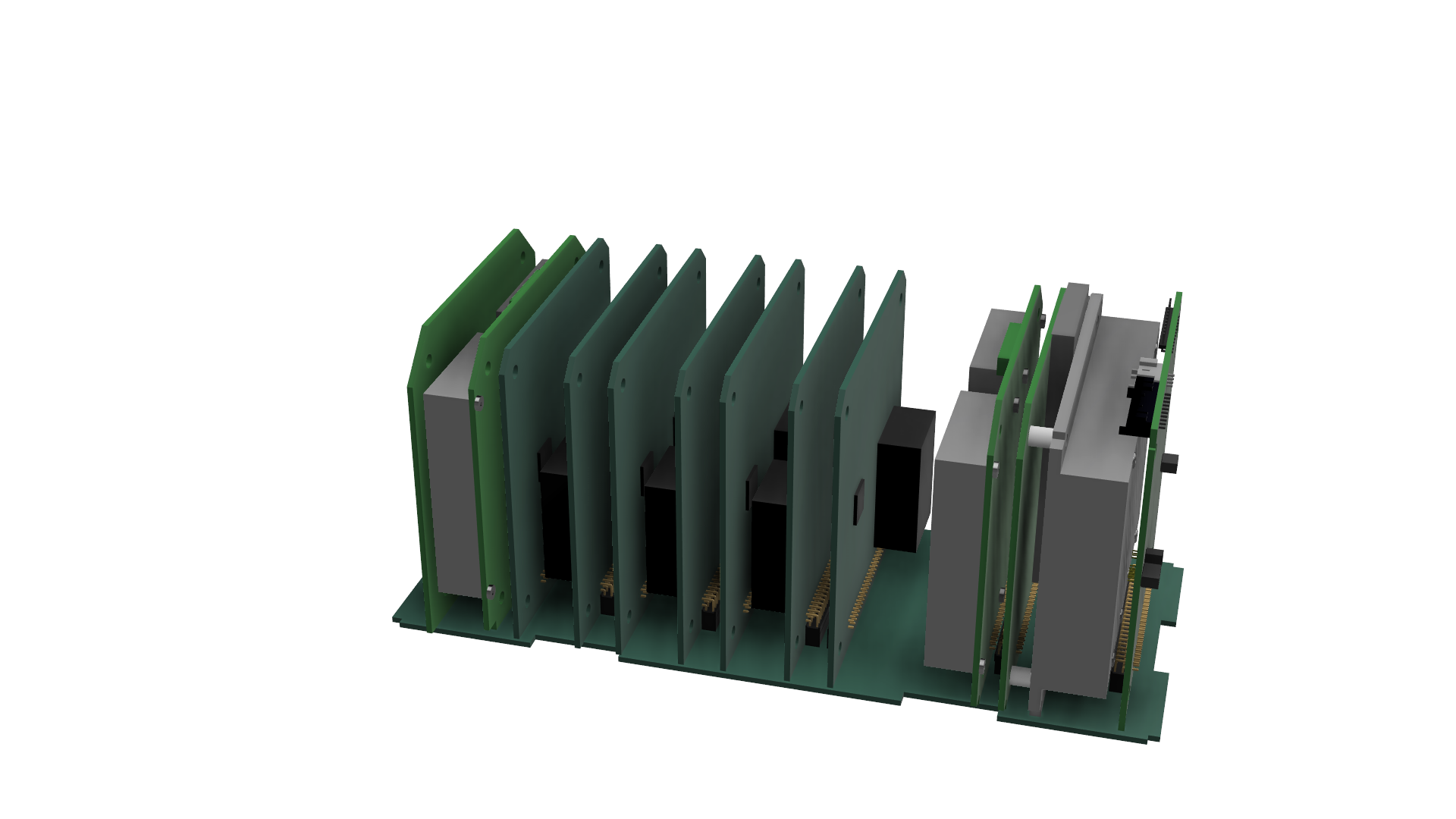
- The bus includes the following key components:
-
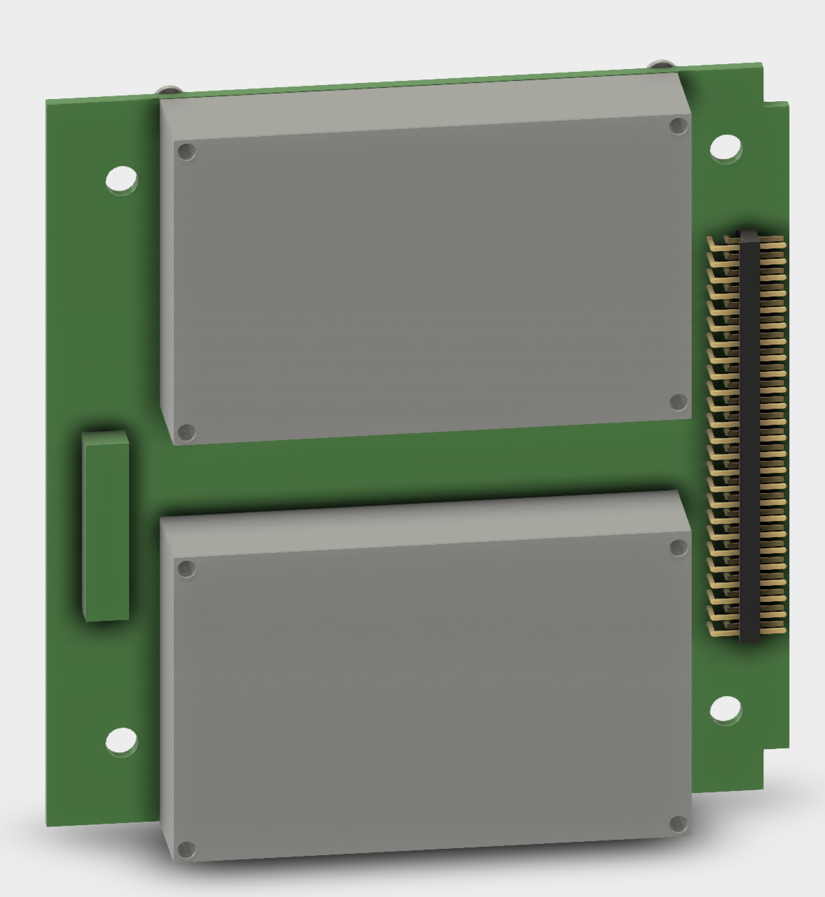
On-Board Computer (OBC): Handles the satellite’s core computing needs. | | | |
| — | :————————————————-: | — | | |  | | - Electrical Power System (EPS): Manages power generation, storage, and distribution.
- Attitude Determination and Control System (ADCS): Controls satellite orientation and stability.
-
Communications (COM): Oversees data transmission to and from the satellite.

-
Structure: Designs and constructs the satellite’s physical frame. | | | | :————————————————– | —————————————————————–: | |  |  |
- Payload: Manages mission-specific instruments or sensors.
- Backplane (BPB): Integrates all the subsystems and allows transfer of power and data to each of them. | | | | |—-|—————————————————-|—-| | |  | |
-
On-Board Computer (OBC): Handles the satellite’s core computing needs. | | | |
Organizational Chart
4. What tools do we use in development?
-
Software:
- Computer Aided Design (CAD) tools for Design: Fusion 360
- Simulation Tools: Thermal desktop, STK for mission analysis
- Programming Languages: C/C++, Python
- Programming Environment: CCS Compiler, MPLAB IDE
- Communication Protocols: UART, SPI
-
Hardware:
- Microcontrollers/Boards: PIC MCUs, custom PCBs
- Power Systems: Solar panels, battery packs
- Sensing Devices: Magnetometers, gyroscopes for ADCS
- Version Control: Git/ GitHub

